Building a Clay Pigeon Remote (part 3): Precision cutting with milling machines

For the past few weeks I’ve considered purchasing a milling machine. These seem to be the best tool for modifying off the shelf enclosures in a non mass produced way. The primary reason for this is that they offer precision and allow for boring into metals and plastics in a variety of different ways.

They are relatively expensive tools for a hobby workshop, a typical pillar drill may cost around £100 (mine cost £120 and when matched up with a steppper drill bit it’s perfect for drilling button holes) but at a minimum a capable desktop milling machine is £800 which seemed quite surprising as my understanding of them is that they are essentially pillar drills with special drill bits and an adjustable base.

However, I’ve come to understand they are far heavier and sturdier machines. This is because a milling machine is required to apply pressure perpendicular to the drill rather than vertically is much more strenuous while at the same time maintain precision.I’m sure there is more to it than that and please feel free to comment and let me know.

I’ve bit the bullet and gone for the Draper variable speed mini mill as it should fit the purpose of cutting accurate shapes into enclosures for rectangular instruments such as lcd’s ad switches. and I look forward to putting it to the test. It should be here by mid April and at that point I’ll give the machine a try write up a review on here. I’m looking forward to it as it’s going to be quite an upgrade from a handheld Dremel!


Shutter Speed Tester

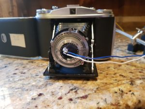
So first of all what is a shutter speed tester? It’s simply a tool that times how long a camera shutter (in the lens) is open for. This is not typically needed for newer cameras as they tend to be accurate. However, older film camera tend to loose their precision due to wear and tear, and exposure settings can be inaccurate. Using a shutter speed tester allows the photographer to gain a true measure of the shutter speed rather than using a trial and error process which can waste film.

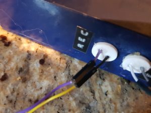
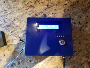
The shutter speed tester has been quite a quick project primarily because it is relatively simple and and it was a case of making alterations to a project developed by c-s-1. These modifications essentially consisted of trimming it down and modifying it to work on a 2 x 16 screen and removing one of the buttons (an lcd light toggle).

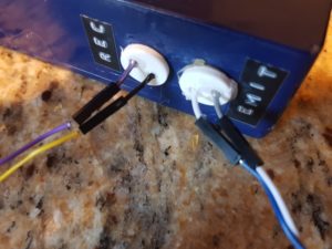
The project is cased in a hammond stomp box enclosure (1590XX) and runs off a dc power supply. If you would like any further information about it to build your own, please get in touch and I’ll fill out the blog with further details.

Here are some potential questions and their corresponding answers

Q: Why is the tester is not picking anything up?

A: There are a few things that need to be checked.

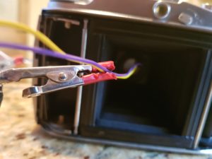
  • Check the receiver and emitters are as close as they can be to the lens. If they are further than a few centimetres from each other the receiver may not pick anything up.
  • Check the wires are actually connected to the right sockets.

Q: The device is giving some random results and I have not used it yet.

A: After you have set it up, before actually using the device, click ‘reset’ it first. During setup the receiver and transmitter can get into contact and give off odd readings.

Gallery

Links index


Building a Clay Pigeon Remote (part 2): Comparing 3D printed and premade enclosures

This blog post is essentially a recount of my experiences trying out 3d printing to make enclosures and may be useful to read if you’ve never made an enclosure before and are thinking about whether to take the 3d printed (printing a box) or ready made route (machining an existing metal box).

When I first started out working with enclosures I typically purchased a handheld enclosure and drilled or cut out each section for the buttons, cable gland, lcd or whaever else warrented the enclosure being cut into.

Due to having few tools and almost always having to make do, the end result always looked terrible with major flaws that really stuck out. Shortly after my first few initial attempts, 3d printers started coming into the mainstream and becoming affordable. I thought this was fantastic, I’d just have to do some CAD designs and the printer would magically produce the thing (I ended up going for the wanhao I3).

It ended up not being quite like that. The CAD software took a couple of weeks to get my head around (Freecad) which is fair. However, while I made some suitable enclosures, they took hours, sometimes days for the printer to produce and if there were any mistakes the whole thing needed to be redone.

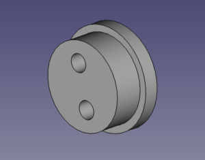
This is the latest example – this is a rotatable model so you can use your mouse to zoom in and out.

The same problem found with enclosures arose again – the quality was not great and after messing up screw inlays multiple times I finally decided it was not suitable. The whole thing seemed too fragile and the amount the filament and electricity cost would come to the same price as a solid aluminum enclosure by Hammond which would be rock solid. That’s not even taking into account the time it takes to built the thing.

So, what next … do a 180 and go back to enclosures.

I knew the issue was precision so after browsing youtube it looked like the way to go was to either have it machined at a manufacturer (expensive and only worth it if you do 100+ enclosures) or draw a stencil, print it out and overlay it on the enclosure. I chose the latter

The next step is cutting out the sections now that the stencil is on. 90% of the sections to be cut were circles. I went all out and bought a pillar drill along with a step drill bit. The pillar drill combined with the stencil and a vice would give the most precision. The only thing better would be a cnc machine (low end models which drill into metal are a few thousand pounds from what I can gather) or sending it off to a fabrication company.

The only time I’d reccomend using a 3d printer is for for smaller components such as mounts. That is if you have a low to mid range printer.

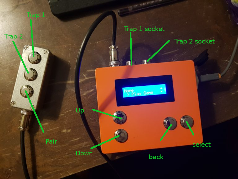
Here’s the latest result which is a clay pigeon remote. As you can see, the sections drilled out are mostly circles (where the pillar drill and step drill bit come into play). Wheras a dremel with a ‘speedclic metal saw’ was used to drill out the square for the lcd.


Building a clay pigeon remote using open hardware (Intro)

A few years ago, myself and a friend purchased a trap from a shooting school that was closing down (North Yorkshire Shooting School).  It came with a basic button switch that released the traps which in essence did the trick in that it released the clays. Nice and simple.

However, we thought about a remote one which allowed for delays, preprogrammed sets and randomly thrown sets. After some searching online we quickly found out these were quite expensive which prompted me to look into alternatives.

As I’d had a play with Arduino microcontrollers before it seemed like the perfect project to learn more about the device and hopefully create a complete product that does the basics but has bells and whistles too.

It’s quite close to being complete now so I thought I’d do a few blogs about some of the key steps involved in its development to demonstrate the progression and hopefully knock out some useful information for anyone interested in developing their own devices. So stay tuned!